Charge Air Cooler Thermal Cycle

Features
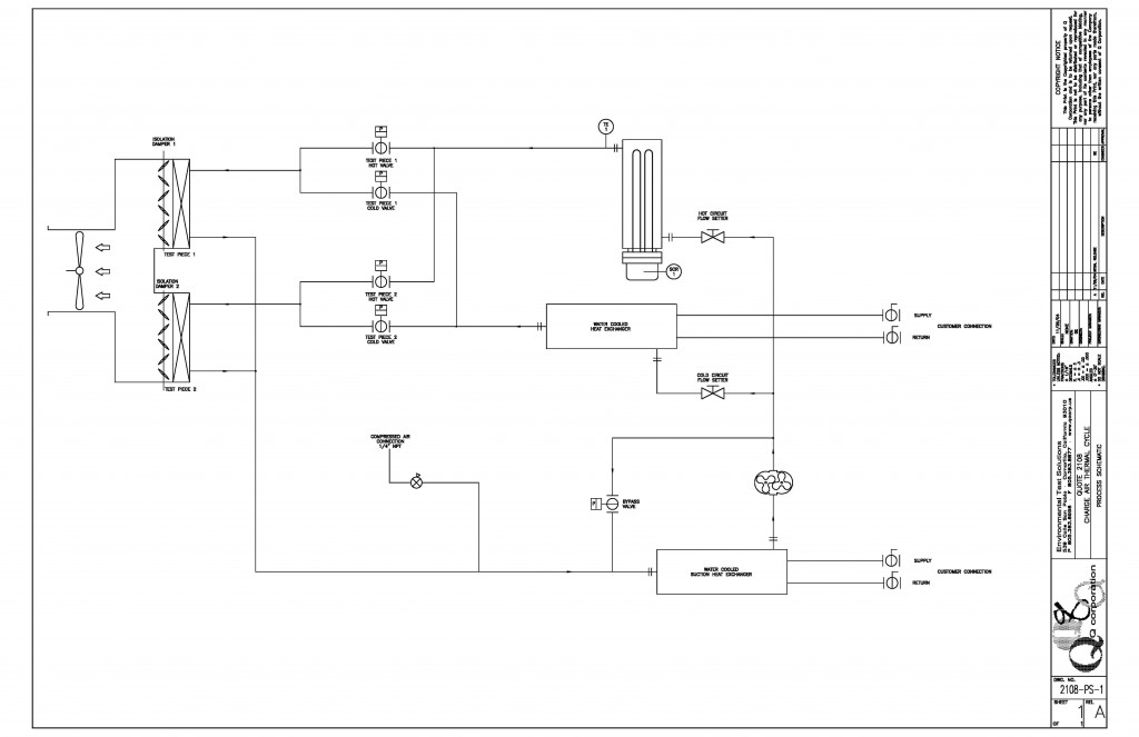
- Q’s standard system will test two-2 UUTs (unit under test) at a time. By design, one unit will operate in a hot cycle, while the counterpart operates in a simultaneous cool cycle.
- The hot circuit will source air from a Q Corp modular charge air supply system (CASS). Once exiting the UUT, the air is further cooled via water to air heat exchanger before returning back to the inlet side of the CASS.
- The surface air (i.e., cool air supply) is routed through an insulated room enclosure. The room is divided into two rooms by a partition in the middle. The units under test (UUT) are mounted on the partition allowing air to pass from one room into the other.
- The open loop cool circuit will source air from the ambient surroundings through a main air supply blower. The air is cooled thru a water to air heat exchanger before entering UUT. Once exiting the UUT, the air is discharged back into the open room environment or ducted to an external location/outside.
Specs
Testing Capacity: 2 parts at a time (standard offering)
Cycle Rate: 30 cycles per hour, typical
Hot Temperature Range: 350° to 700°F+
Cool Temperature Range: Water supply temperature + 12°F to 130°F
Temperature Stability: +/- 10°F
Charge Air Airflow: 10 to 150 lb./min per Unit
Charge Air Supply
Rotary Vane Blower
Variable Speed Drive
Maximum Pressure Drop 6 psi
Temperature Range: Ambient
Control Interface
5,000 to 10,000 cfm
airflow based on cooling requirements
Surface Air Supply
Vane Axial Blower
Variable Speed Drive
Maximum Pressure Drop: 4” Water Column
Digital Control and Alarming
Allen-Bradley Micrologix PLC
PIDs internal to AB 1500
Controllers: Internal to PLC
Digital Outputs: System Alarm, (120V AC)
Communications: RS-232